Links to sections on this page:
To a large degree, the vertical acceleration of an air parcel results from an imbalance between two, usually opposing forces: the vertical pressure gradient force and the buoyancy force. A pressure gradient is the difference in pressure between two places divided by the intervening distance. A parcel is said to be positively buoyant when it is less dense than its surroundings. If the parcel and environmental pressures are the same, this can result from the parcel being either warmer and/or more moist than the environment. Horizontal accelerations result from horizontal pressure gradients.
Pressure may be subdivided into dynamic and buoyancy components. Dynamic pressure is associated with wind velocity gradients. A familiar example is the low pressure (surface depression) created when the fluid in a teacup is stirred. Buoyancy pressure is associated with buoyancy gradients. Thus, pressure gradients themselves may be apportioned into gradients owing to the dynamic and buoyancy components. The vertical gradient of buoyancy pressure usually opposes the buoyancy force.
The horizontal acceleration of a parcel, PUDT, may be written as PUDT = Fdx + Fbx, where the "Fdx" and "Fbx" acceleration components consist of the horizontal gradients of dynamic and buoyancy pressure, respectively. Similarly, the vertical parcel acceleration, PWDT, is PWDT = Fdz + Fbz, where now "Fbz", the vertical component of buoyancy acceleration, combines the vertical buoyancy pressure gradient ("DPBDZ") and the buoyancy force ("BUOY") per unit mass.
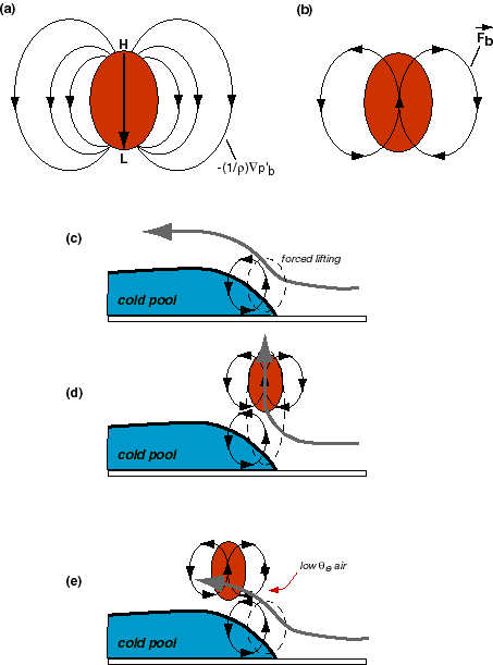
The horizontal and vertical buoyancy accelerations may be combined and presented as a vector that will be referred to as Fb. This vector field denotes not how air is moving but rather how air is being accelerated due to the combination of buoyancy pressure and buoyancy forces. The figure below describes how this field will be used to interpret why cells are discrete and short-lived.
Panel (a) below sketches the circulatory tendency in and around a positively buoyant parcel owing to the buoyancy pressure. A rising parcel induces high pressure above it, and low pressure beneath. Thus, within the parcel, there is a buoyancy pressure gradient directed downward from high to low. This downward acceleration slows, but typically cannot restrain, the upward acceleration driven by the positive buoyancy. Downward accelerations are also induced outside of the parcel. For rising motion, there must be compensating descent; this is how the required downdrafts become established.
When the buoyancy pressure accelerations are combined with the buoyancy force itself, the circulatory tendency depicted in panel (b) results. Upward accelerations dominate inside the buoyant parcel while the downward accelerations established on the parcel's flanks have gone unopposed. Vectors of Fb are parallel to, and thus outline, the buoyancy-induced circulation.
In panel (c) above, the buoyancy-induced circulatory tendency associated with the buoyancy contrast across the cold pool nose is depicted, as well as the pool-relative flow. The cold pool is spreading upwind, underrunning the warmer, more moist air that comprises the storm inflow. This storm inflow air is lifted (creating the forced updraft), but it is also accelerated towards the storm's rear by the buoyancy-induced circulation.
Condensational latent heat release has a first-order effect, but one that is very sensitive to where the heating takes place relative to the forced lifting. When the cell is newly established, the heating takes place above the cold pool nose, as shown in panel (d). The cell's buoyancy-induced circulation helps to intensify the forced lifting (drawing air upward) while it partially suppresses the tendency for air to be accelerated rearward. During this period, the new cell intensifies quickly. An air parcel entering the forced updraft at this time is primarily accelerated upward.
The cell soon begins drifting rearward, however, owing to the front-to-rear momentum of the inflowing air in which the cell is embedded. As it shifts its position, effect of the cell's buoyancy-induced circulation on the forced lifting goes from being constructive to being destructive. An air parcel entering the forced updraft at this time is rather quickly driven rearward, without being given much of a chance to rise.
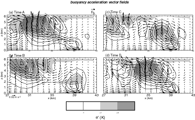
The figure above presents the Fb buoyancy acceleration fields for four times spanning one cell generation cycle. These vectors show not how air is moving, but rather how air is being accelerated owing to the buoyancy field. Also, since dynamic and other contributions to the total acceleration are ignored, this is an incomplete picture of the total acceleration field. The shaded field superposed depicts perturbation potential temperature.
In panel (a), the pronounced circulatory tendency on the right flank of the cell above x=33 can be seen. This cell is rapidly intensifying at this time. However, its own circulation is doing two things:
The growing cell's suppressing effect on the forced updraft wanes, however, as the cell moves towards the rear of the storm. By the time of panel (b), the forced updraft has already begun to reintensify. The presence of positive perturbation potential temperature values in the upper portion of the forced updraft indicates that condensation warming has already begun. Yet another new cell has been created, but this did not happen until the older cell managed to "get out of the way".
In the remaining two panels, note how rapidly the just-established cell intensifies and also how quickly its own buoyancy-induced circulation starts working against it. The paper also presents vector fields of the total acceleration, representing the combination of the buoyancy and dynamic acceleration components.
New cell establishment usually does not occur until the suppressing effect of the previously established cell's circulation has waned (typically as a result of that cell having translated farther rearward). Once the suppression has been removed, a new cell may or may not be formed in the vicinity of the forced updraft. How quickly the new cell becomes established (if indeed this occurs) is probably a complex function of many factors.
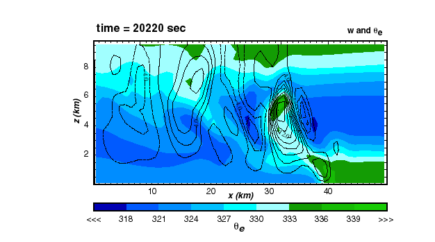
In this case, new cell generation was accelerated by the presence of a convective trigger in the storm's inflow environment. This trigger appeared as a transient, localized increase in the depth of the high qe layer feeding convectively unstable air into the storm. The figure below presents the qe field at four times during the cell generation cycle, and the arrows mark the location of the elevated layer. These fields were animated in this movie, originally linked to the cell generation discussion on the previous page.

The elevated layer appears to become established as a result of the previous cell's buoyancy-induced circulation. The forced lifting starts reintensifying around the time of panel (b) in the figure above. By the time of panel (c), its circulation has established a downdraft on the growing cell's right (east) side. This downdraft pushes low qe air from the middle troposphere down, causing the high qe layer immediately beneath it to become shallower. Horizontal convergence just upstream (again, east) of the downdraft induces the deepening of the unstable layer marked by the figure's arrows.
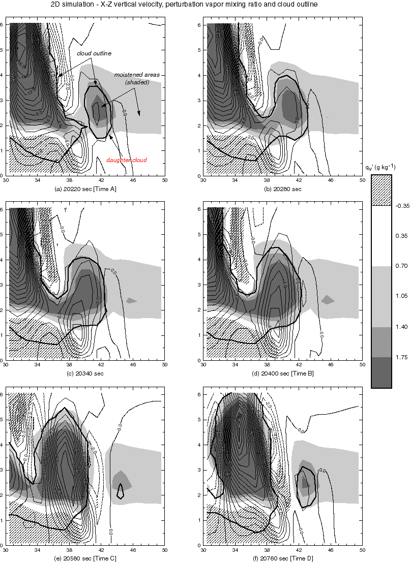
We call the elevated qe layer feature a "convective trigger" because it appears to hasten the establishment of the next cell. Note in the above figure that rapid reintensification of the forced lifting occurs when the elevated layer passes over the forced lifting's location. The paper's Figure 15, a copy of which is linked here, shows a close-up view of this process. The shaded field is perturbation water vapor mixing ratio, with the darkest shading indicating where air the most moistening has taken place. The cloud outline and vertical velocity fields are superposed. This figure is described further below.
At the top of the elevated high qe layer, air is being brought to saturation, resulting in the establishment of a shallow "daughter cloud". In this case, the daughter cloud is merely the visual signature of the elevated layer. The daughter cloud is embedded in a storm-relative airflow that carries the cloud towards the forced updraft after establishment. Note as the daughter cloud passes just over the forced lifting, the latter starts growing rapidly, almost as if a lighted match were brought over a gas burner. It is likely that the forced updraft would reintensify anyway, but it appears that the time interval required has been shortened by the convective trigger represented by the daughter cloud. Indeed, as shown in the last few panels, it is the rapid growth of the just-established cell that helps create the conditions leading to the appearance of the next daughter cloud.
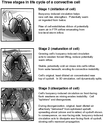
The figure below summarizes the three stages in the life cycle of a convective cell. A fourth and final stage, marking when the cell becomes convectively inactive, could conceivably be added. The shaded field is qe, and the cell's buoyancy-induced circulations are superposed. Note the reference frame depicted is not fixed in space, but rather tracks the cell's principal updraft as it moved upward and rearward within the storm.
Page created March, 1999, by
 Robert Fovell